Control of Frequency Inverters and Voltage Controllers using the ORe 5 Remote Controller
Control of Frequency Inverters and Voltage Controllers using the ORe 5 Remote Controller
Frequency inverters delivered by Remak a.s. offer two methods of control: using a 0-10V control signal or combined switching of three non-potential contacts. The control mode option can be set in the frequency inverter menu.
Transformer TRN controllers can only be controlled by the combined switching of three non-potential contacts; direct use of a 0-10 control signal is not possible.
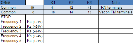
The switching combination can be generated either directly by the control unit or the ORe 5 controller. These combinations are fixed; any other combination than those below results in STOP. The combinations for individual output stages are the same for TRN controllers as for frequency inverters. In practice, this means that the +24 V control signal from the common terminal (49 - TRN, 6 - FM) is supplied to the individual outputs (41, 42, 43 - TRN, 10, 14, 15 - FM).
In addition to the switching of the required combination, it is necessary to switch the START command:
- by closing terminals 6 - 8 when the frequency inverter is used

- by closing terminals 46 - 47 when the controller is used; if terminals 47 - 48 are closed, the controller is either switched off or reset

Vacon frequency inverter and the ORe5 controller wiring diagram
The frequency inverter is not prepared for the motor thermo-contact connection. This must be ensured in some other way (e.g. STE, STD protective relay)
TRN controller and the ORe5 controller wiring diagram
When connected in this way, the controller works not only as an output controller but also monitors the thermo-contacts, and when they open the controller ensures disconnection of the motor power supply. When the controller is associated with a control unit, the thermo-contacts are monitored by the control unit while the controller then works only as an output controller. If this is the case, all safety functions of the controller must be blocked by interconnecting the 48 and PT2 terminals. A specific wiring diagram is always delivered with the control unit.
Wiring diagram of two Vacon frequency inverters connected to the ORe5 controller
Wiring diagram of two TRN controllers connected to the ORe5 controller
As can be seen in the wiring diagram, the +24 V control voltage is supplied from only one controller (terminal 49), respectively from one frequency inverter (terminal 6). The other controller (inverter) terminal will not be connected.